
Location
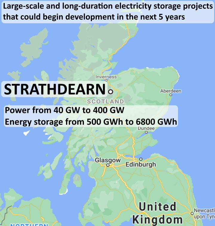
The map shows how and where the biggest-ever pumped-storage hydro-scheme could be built – Strathdearn in the Scottish Highlands.
Energy storage capacity
The scheme requires a massive dam about 300 metres high and 2,000 metres long to impound about 4.4 billion metres-cubed of water in the upper glen of the River Findhorn. The surface elevation of the reservoir so impounded would be as much as 650 metres when full and the surface area would be as much as 40 square-kilometres.
The maximum potential energy which could be stored by such a scheme is colossal – about 6800 Gigawatt-hours – or 283 Gigawatt-days – enough capacity to balance and back-up the intermittent renewable energy generators such as wind and solar power now in use for the whole of Europe!

 Transmission losses

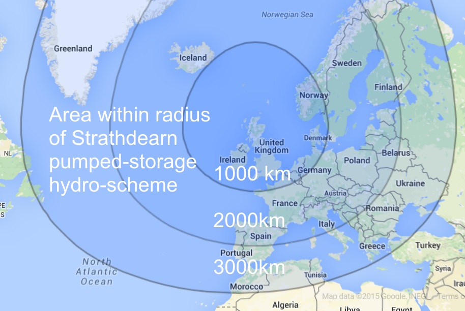
Most of Europe is within 3,000 km of Strathdearn meaning that one-way transmission losses to or from anywhere in Europe could be as low as 10.5% using existing high-voltage (800 kV), direct current (HVDC) electric power transmission system.
In theory, transmission power losses are inversely proportional to the voltage-squared so it is possible that if and when even higher voltage than 800 kV transmission technology were to be developed, transmission losses could be reduced still further.
Transmitting power at 800 kV to and from a well-designed efficient pumped-storage hydro-scheme, two-way transmission losses are
- at distances of 2000 km to 3000 km, from 14% to 21% and represent the single most significant loss factor, indicating that 800 kV is an inappropriately low transmission voltage for service at this distance – 800 kV at this distance is not recommended but possible meantime if and while no better option is available
- at distances of 1000 km to 2000 km, from 7% to 14% and so the losses at the pumped-storage hydro scheme itself are likely to be the single most significant loss factor – 800 kV at this distance is not ideal, may be practical but reconsider if and when there are any better options
- at distances of less than 1000 km, less than 7% and so losses are acceptable – 800 kV at this distance is ideal and recommended for full service life for Scotland, England, Wales, Ireland, southern Norway, Denmark, north-west Germany, Netherlands, Belgium and northern France.
Power
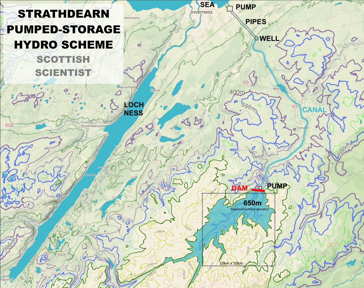
There would need to be two pumping and turbine generating stations at different locations – one by the sea at Inverness which pumps sea-water uphill via pressurised pipes to 300 metres of elevation to a water well head which feeds an unpressurised canal in which water flows to and from the other pumping and turbine generating station at the base of the dam which pumps water up into the reservoir impounded by the dam.

using a STEPPED CANAL and ARCHIMEDEAN SCREW PUMP-TURBINES
To fill or empty the reservoir in a day would require a flow rate of 51,000 metres-cubed per second, the equivalent of the discharge flow from the Congo River, only surpassed by the Amazon!
The power capacity emptying at such a flow rate could be equally colossal. When nearly empty and powering only the lower turbines by the sea, then about 132 GW could be produced. When nearly full and the upper turbines at the base of the dam fully powered too then about 264 GW could be produced.
Modelling of a wind turbine power and pumped-storage hydro system recommends –
- store energy capacity = 1.5 days x peak demand power
suggesting that a store energy capacity of 283 GW-days would be sufficient to serve a peak demand power of 283 / 1.5 = 189 GW, though this could only be produced from reservoir heads of at least 430 metres, at least 8% of energy capacity, assuming a flow rate of 51,000 m3/s. To supply 189 GW from the lowest operational head of 300 metres would require increasing the flow capacity to 73,000 m3/s.
This represents many times more power and energy-storage capacity than is needed to serve all of Britain’s electrical grid storage needs for backing-up and balancing intermittent renewable-energy electricity generators, such as wind turbines and solar photo-voltaic arrays for the foreseeable future, opening up the possibility to provide grid energy storage services to Europe as well.
Canal
The empirical Manning formula relates the properties, such as volume rate, gradient, velocity and depth of a one-directional steady-state water flow in a canal.

For 2-way flow, the canal must support the gradient in both directions and contain the stationary water at a height to allow for efficient starting and stopping of the flow.
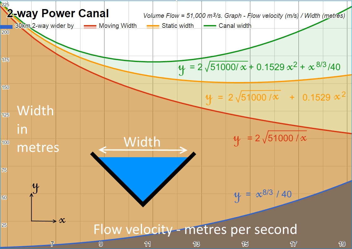
The “2-way Power Canal” diagram charts from a spreadsheet model for a 51,000 m3/s flow how the width of the water surface in a 45-degree V-shaped canal varies with the designed maximum flow velocity. The lines graphed are
- Moving width – from simple geometry, for a constant volume flow, the faster the flow velocity, the narrower the water surface width
- Static width – the width of the surface of the stationary water with enough height and gravitational potential energy to convert to the kinetic energy of the flow velocity
- 30km 2-way wider by – using the Manning formula, the hydraulic slope can be calculated and therefore how much higher and deeper the water must begin at one end of a 30km long canal to have sufficient depth at the end of the canal and therefore by how much wider the canal must be
- Canal width – adding the 30km-2-way-wider-by value to the static-width determines the maximum design width of the water surface.
The equation thus derived,
y = 2 √ ( 51000/x) + 0.1529 x2 + x8/3/40
where y is the maximum surface water width in the canal and x is the designed maximum flow velocity
predicts a minimum value for the canal width of about 170 metres (plus whatever additional above the waterline freeboard width is added to complete the design of the canal), containing up to 216 million cubic-metres of water, at a design maximum flow velocity between 10 and 11 metres per second, similar to the velocity of the 2-way flow of the fastest tidal race in the world at Saltstraumen, Norway.
Video of the tidal race at Saltstraumen
Guinness World Records states that the widest canal in the world is the Cape Cod Canal which is “only” 165 metres wide.

The construction of the Panama Canal required the excavation of a total of 205 million cubic-metres of material but the Strathdearn Power Canal would need more excavating and construction work than Panama did.

So the Strathdearn Power Canal, too, would be the biggest ever!

Canal efficiency
To improve the power canal’s energy efficiency requires designing for a slower maximum flow velocity which requires a wider moving and static width of the water surface to maintain the maximum volume flow rate which –
- increases the canal’s construction costs
- decreases the canal flow’s hydraulic slope
- decreases the canal’s 2-way hydraulic head height loss, at most equal to the 30km-2-way-wider-by
- decreases the canal’s energy loss
- increases the canal’s energy efficiency
So a wider canal would be more expensive to build but would be more energy efficient in use, saving energy costs over the longer term. A wider canal also allows for a higher flow rate. For example, 62,000 m3/s – which could be useful to power 159 GW when the reservoir was running low, assuming additional turbines were installed for such a purpose – would require a minimum canal width of 182 metres.
For a minimum canal width of 170 metres and a flow rate of 51,000 m3/s, implying a maximum flow velocity of 9.8 m/s, the 30km-2-way-wider-by is 11 metres so the maximum 2-way hydraulic head height loss as a proportion of the reservoir operational head heights from 300 to 625 metres would represent an energy loss from 11/625 = 1.8% to 11/300 = 3.7%, averaging presumably somewhere around 11/462 = 2.4%, estimating the power canal to be about 97.6% efficient when operated at full power and even more efficient at reduced power. The follow table indicates how energy efficiency increases with canal width.
Table of canal efficiency for a flow rate of 51,000 m3/s
| Width (m) | 2-way head loss (m) | Energy loss | Efficiency |
|---|---|---|---|
| 170 | 11.1 | 2.4% | 97.6% |
| 180 | 5.1 | 1.1% | 98.9% |
| 190 | 3.3 | 0.72% | 99.3% |
| 200 | 2.3 | 0.51% | 99.5% |
| 210 | 1.7 | 0.37% | 99.6% |
| 220 | 1.3 | 0.28% | 99.7% |
| 230 | 1.0 | 0.22% | 99.8% |
Canal lining and boulder trap

To maximise the water flow velocity, canals are lined to slow erosion. Concrete is one lining material often used to allow for the highest water flow velocities, though engineering guidelines commonly recommend designing for significantly slower maximum flow velocities than 10 m/s, even with concrete lining.
Water flowing at 10 m/s has the power to drag large – in excess of 10 tonnes – boulders along the bottom of a canal with the potential of eroding even concrete, so I suggest that the bottom 6 metres width of the lining, (3 m either side of the corner of the V) may be specially armoured with an even tougher lining material than concrete and/or include bottom transverse barriers of 2 metres depth to impede the flow along the corner of the V and trap boulders, smaller stones and gravel, in which case the water flow is more precisely modelled for Manning formula calculations as a trapezoidal canal with a bed width equal to the 4 metre width of the top of bottom transverse barrier (“boulder trap”) and a 2-metre smaller depth from the top of the boulder trap to the water surface.
Main Dam

The image shows the location of the main dam at latitude 57°15’16.2″N, decimal 57.254501°, longitude 4°05’25.8″W, decimal -4.090506°.
Assuming the dam would be twice as wide as its height below the dam top elevation of 650 metres, the superficial volume is estimated at 80 million cubic metres, not including the subterranean dam foundations which would be built on the bedrock after clearing away the fluvial sediment.
Geology

The image shows an extract from the British Geological Survey’s bedrock map overlaid upon my plan for the Strathdearn Pumped-storage hydro scheme. Readers are referred to the BGS’s Geology of Britain viewer for details.

When the facility is generating, will there be problems maintaining the required flow along the canal to maintain the head in the Inverness pipe/generator? Assuming the goal would be to be able to generate a few GW, I wonder if the design would need to include a quite-large holding pool at the Inverness end of the canal?
LikeLike
David,
I’m honoured to welcome your first comment on my blog – the first of many I hope. Your book – “Sustainable Energy – without the hot air” by David JC MacKay is the 2nd-most quoted reference source (after Wikipedia) in the online discussions I have been party to regarding renewable energy, especially your Chapter 26 “Fluctuations and storage” in the context of pumped-storage hydro.
I rushed this post out in the early hours of this morning because I am keen to share my design concept at the earliest opportunity regardless that many key details of my proposal remain unspecified in the post at this time (15 April 2015). I intend to update this post on my own initiative and in answer to comments such as yours.
The most important missing detail in the first draft of this post is (was) any estimate for the power capacity. Whilst we may agree that power capacity should be in proportion to the energy storage capacity, we may differ on precisely what constant of proportionality to recommend.
On page 189 of your book, you recommend storage capacity equivalent to 5 days of average power. Attempting to follow the guidance in your book, from an energy storage capacity of 100 GW-days, would not your book’s recommendation for power capacity be the peak power equivalent of 20 GW average power (1.6 x 20 = 32 GW peak power) or for 200 GW-days energy storage then the peak power equivalent of 40 GW average power (1.6 x 40 GW = 64 GW peak power), which is a lot more than “a few GW”?
Peak-power is the more relevant nameplate specification for a pumped-storage hydro-scheme because pumps and turbines must be able to handle peak power, not only average power.
In my blog post “Modelling of wind and pumped-storage power” I modelled a smaller constant of proportionality for energy storage capacity of only 1.11 peak-demand-days (equivalent to 1.6 x 1.11 = 1.77 average power-days), with satisfactory results. So, as of now, I’m recommending only “1.77 days” equivalently compared to your “5 days”, a constant of proportionality of about a third of yours.
Accordingly, I’d recommend for 100 GW-days, a nameplate peak power capacity of 100 / 1.11 = 90 GW, and for 200 GW-days, 180 GW. As you can see this is considerably in excess of UK peak demand of 60 GW, opening up the possibility to provide grid energy storage services to Europe as well.
Those figures had to be discussed first before turning to the requirements for water flow through the pumps, the pipe and the canal because all of the features of the hydro scheme must be scaled appropriately.
The required flow rate of water can be calculated, as you know, from the head and the power capacity and the empirical Manning formula may be used to design the cross-sectional area of a canal to achieve the required flow rate.
So to get to your question David, yes there would indeed be problems in maintaining the required flow along the canal to maintain the head – at both ends because flow is in both directions – but a holding pool at either end, however large, would not solve those problems. Only a canal of a sufficient cross section with additional design features as required could hope to do so.
I’ve not done any estimates for the required minimum cross section of the canal as yet but that’s of interest certainly.
Once again, David, I must tell you how ‘fair chuffed’ I am that you commented on my post!
LikeLiked by 1 person
As it’s only 16 metres above sea level, I’d say it would be highly desirable to use Loch Ness as the lower reservoir, so that the entire system is fresh water.
I agree with David Mackay, continuous pipes or tunnels bored through the mountain would seem to be the best option to connect upper and lower lochs. To my knowledge, all existing PHS uses that design principle. Is the flow capacity an issue here?
The main problem I see, aside from the undoubtedly high cost and objections to flooding a valley, would be the massive transmission capacity required to make this scheme work. The proposed NorthConnect cable is costed at £1.7bn for 1.4GW. I must say, the idea of selling Scottish wind power to Norway and buying it back at a higher price strikes me as ridiculous.
LikeLike
Hi Dave and thanks for your comment.
Such is the volume of water in the reservoir were it to be emptied into Loch Ness, it would massively flood Loch Ness and flood the surrounding land.
Likewise, filling the reservoir up from Loch Ness would drain Loch Ness and soon leave the pumps running out of water to draw in. The problem arises because the volume of the reservoir would be comparable to the volume of Loch Ness. For such a large reservoir, the Scottish lochs are simply too small to serve as the lower reservoir.
I think my canal concept may be somewhat new in the context of pumped-storage hydro schemes, yes.
Flow capacity is indeed an issue with attempting to go very far underground because of the size and number of tunnels required. As you can read in the updates to the post, the canal I have designed to carry the full flow would be the biggest-ever.
I’ve not filled in the details for the “pipe” indicated in the map but I think I may be straying into “biggest-ever” territory again. Going underground may not the best solution here. Perhaps extending the canal concept to go over the surface to the sea, including a number of smaller hydro-schemes steps on the way, may be the way to go?
The required transmission capacity would be massive too, admittedly.
Pumped-storage schemes buy power when it is cheap – when the wind is blowing a gale or the sun is blazing – and sell it when it is more expensive, when it is calm or dark, not the ridiculous other way around.
Norway is very well served with pumped-storage, as is Sweden (Edit: Swedish hydro-schemes which could be upgraded to PSH operation), so the market for European grid energy storage services is likely to come from elsewhere in Europe.
LikeLike
Thanks for your response. I think that working out the rough intended flow rate and required cross-section is a priority. My guess (without having done the Manning calculation either!) is that your canal’s cross-section (in the current design) would have to be unrealistically large; but if you redesigned to include holding ponds (sized to be able to serve up say 6 hours of water without significant loss of head) then maybe you could get by with a more realistic canal. Let me know when you’ve done the Manning thing!
My instinct is that this issue I’m raising is critical, and it might be best to focus on locations where a continuous pipe can be bored or laid all the way from top loch to the bottom. I think there are lots more places in the Highlands where mega-reservoirs could be created.
LikeLike
David,
I’ve updated my post to include more detailed estimates for the reservoir volume, maximum flow rate, energy storage and power capacity.
I’ve also used the Manning formula to estimate a canal size to cope with the maximum flow rate and as with seemingly everything else in this design, the canal too is “unrealistically” large.
I think your “holding ponds” idea and smaller canal would turn my well-thought-out design into a cobbled-together system performing essentially not unlike two normally-powered separate pumped-storage schemes – the lower sea-side scheme limited by its smaller holding pond for an upper reservoir and the upper dam-side scheme limited by – presumably – its own holding pond near the base of the dam functioning as the pump-at-the-base-of-the-dam’s lower reservoir?
The sizes of both holding ponds would severely limit the power and energy capacity performance of the scheme as a whole and defeat the whole purpose of a design incorporating such a big reservoir. So no David, I don’t support your holding ponds idea but will stand by my concept for a canal to carry the full flow of the scheme at full power.
As I think we’d agree, the location of the upper reservoir is just too far from the sea to go underground all the way but my opinion is that it is such an exceptional site for a such a big reservoir that I think it is worth figuring out a design to get maximum power from it and the biggest-ever canal is my solution.
I’m not stuck for design ideas but I do appreciate your interest, David. Thank you very much.
LikeLike
Here’s another possible location for putting a big big dam.
https://maps.google.co.uk/maps?ll=56.903941,-5.57333&spn=0.066927,0.171146&t=p&z=13
I’ve zoomed in on a possible location for a 1.2km long dam here:
https://maps.google.co.uk/maps?ll=56.913501,-5.616417&spn=0.016727,0.042787&t=p&z=15
The lake that would be very significantly deepened is Allt a choire.
LikeLike
David, I have come across another proposal for a pumped-storage hydro-scheme which uses much the same location as you have identified in your comment.
Energy Storage Solution for the UK: Large Scale Pumped-Storage Site – by Julian Hunt – published on The Energy Collective – the world’s best thinkers on energy and climate.
I can see from your book that you had scoped Loch Morar out as one of your 13 potential sites for pumped-storage.
Figure 26.10. Lochs in Scotland with potential for pumped storage – from Sustainable Energy – Without The Hot Air – by David MacKay.
Did you have in mind, as Julian Hunt does, using Loch Morar, immediately to the north, as the lower reservoir?
The upper reservoir which is only identified on Google maps with the text Allt a’ Choire is named on another map as Loch Beoraid.
Julian Hunt suggests using Loch Morar sufficiently drained so that its lowest level in use would be minus 300 metres below sea level.
Were you of a mind to use Loch Morar without prior draining it so low?
Julian Hunt reckons he can get 1300GWh energy storage capacity with a 300 metre dam and 1800GWh with a 350 metre dam.
My own modelling indicates that a capacity of 1,400 GWh would be appropriate to serve all of the UK’s needs for energy storage for an essentially renewables-only generation capacity to serve all of the UK’s electricity demand, without nuclear or fossil fuel power stations, except perhaps mothballed for emergency power.
So a claim of “1,300 GWh” is of interest. As is Julian’s further claim of “1,800 GWh” with a higher dam.
I can identify some issues and questions now with Julian’s proposal which are mainly to do with the lower reservoir.
1) The surface area of the lower reservoir when drained to a depth of -300 metres and therefore the volume which can be lowered to that depth is likely to be small.
It would be nice to read some of Julian’s thinking as to what assumptions he made to get to the 1,300 GWh or 1,800 GWh figure.
2) There would be a greater difficulty in sealing the lower reservoir from ingress from sea water from factures in the bedrock.
Sealing water in to an upper reservoir is not too hard because the water pressure forces the sealant further into the fractures.
But in the lower reservoir, any sea water ingress will be forcing any sealant to pop out of the fractures which makes sealing much more difficult.
This is not an insurmountable problem for tunnels which go under seas or rivers and mining operations below sea level but is a lot easier if the bedrock is impermeable to start with – otherwise pumping out continuously may be the obvious solution but that takes energy, not an issue unless that energy is too high, which it could be in this case but I don’t know.
I wonder if Julian has worked out a figure for the energy it would take to drain the lower reservoir of the water to the sea which could not be contained in the upper reservoir? The operators would not want to be wasting energy bailing the lower reservoir out of sea water too often.
LikeLike
Physics, and even civil engineering, is a lot easier than economics and politics.
What would be the capital cost, delivery time, and return on capital of this project?
The present instability of the United Kingdom militates against any major new central investment north of the border (some of us remember the nationalisation of the Suez Canal) so the project must either be funded from taxes raised in Scotland or entirely from private venture capital. It would be difficult to sell a project to the Scottish Parliament where the intended principal beneficiaries would be in England (Scotland probably doesn’t need this project at all, and certainly not on this scale), and difficult to pitch for private capital if there is no chance of a 20% per annum return witin 5 years.
Since the project only generates revenue when (a) the grid is heavily dependent on unreliable sources of power (b) there is sufficient overcapacity of free power to recharge the reservoir whilst meeting current demand and (c) those sources have failed, how do we avoid a chicken and egg situation? Existing pumped storage systems of any significant size have been built as part of a planned and integrated generating and transmission system but the modern political trend is towards relatively small, private, opportunistic generators and there is almost no recent history of significant grid-sourced storage.
Longterm, say over the next 50 years, wind power and some form of storage makes a lot of sense, but neither governments nor modern capitalists tend to think beyond the next general election.
LikeLike
Hi Alan and welcome to my blog after we replied to each other in the “How can renewable energy farms provide 24-hour power?” topic in the University of Cambridge’s “The Naked Scientists” forum, where you made a similar point.
alancalverd
"Scale is important because this project requires capital input. There is obviously no physical reason why it can't be done but the practicality is that you need enough money up front to start the work, with a sufficient promise that it will be funded to completion. Failing that, a project will run into the sand as lack of continuing funding means delay, which increases costs and makes further funding less attractive.Whilst Scottish independence remains a serious possibility, it won't be funded by the UK government, so the money has to be raised either by private investors or by taxing the Scots for long enough to build up the required capital reserve (and not spending it on something else, which politicians are bound to do)."
Scottish Scientist
“I think the way to build this is not all at once but first to build part of the sea-side scheme, using a length of canal as an upper reservoir.
Get a system working for Scottish 2020 renewables-only needs then once the team which has done that has a working scheme in place, hopefully the investment to complete the rest of the sea-side scheme and the reservoir and dam-base pumps would become available.
That way at least we’d have working pumped-storage to show for any investment if the money ran out before final completion.”
alancalverd
"So, let's have some cost estimates, please!"Scottish Scientist
“8 GW / 8.5 GW-days – £5.4 billion (Scottish needs demonstrator project, using about 20km of canal as the upper reservoir)
264 GW / 280 GW-days- £180 billion.”
As for delivery time, that depends on how quickly the money is spent.
Government deficit spending could finance the entire project so private capital would not be necessary but could be attracted by a government-guaranteed return on any private capital invested.
I take inspiration from the many collaborative international projects – the international space station, CERN – the European Organisation for Nuclear Research, the Channel Tunnel, Concorde, Airbus etc.
Politically independent countries and the devolved countries within them do find a way to give permission to, to fund, to build and to run mutually advantageous projects which span international borders, government term limits and bank loan repayment dates.
Where there is an international will, there is an international way.
I think the people of many countries do appreciate the efforts of scientists and engineers to innovate with a view to providing clean renewable energy which protects the environment.
That’s why I have presented this plan and why I think it may be considered respectfully and be given a fair wind, by Scots, by Britons and by Europeans and in due course by their elected representatives and governments. This would be a project which would need government backing and indeed bankrolling to proceed to construction.
You are one of those who has remembered Suez Alan but are you also one of those who has learned nothing from it?
If I may digress to teach as a social scientist, the UK remembers its history with pomp, circumstance and flummery but is ignorant when it comes to learning the appropriate lessons from the events it remembers so well.
The lesson to learn from Suez is that the UK’s error has been sometimes to pursue the opposite approach to international collaboration.
Rather the UK has sometimes resorted to the dangerous approach of imperialism, overriding national sovereignty by brute force
– overriding Egypt’s national sovereignty in the crisis over the Suez Canal
– overriding Britain’s national sovereignty and the sovereignty of the home nations as our soldiers were dragged ineptly into the imperialist conflict over the Suez canal.
The UK is, by definition, a kingdom and therefore a bastard state, a creature of the monarch and not a nation state democratically accountable to the people.
So the UK is institutionally unwilling to educate the people about the difference between the nation and the state because to do so would lead the people to question the legitimacy of the UK’s own existence.
Here is the difference between the “nation” and the “state” for you to learn Alan.
The state does what PM Cameron or FM Sturgeon decides or what the UK’s judges or other officials decide.
The nation supports what the nation’s people freely support – “freely” meaning not only on election day, not by brainwashing the people via state control of broadcasting and not by arresting those who vociferously dissent.
The successful projects are those which win the support of all of the collaborating nations, all of the people who are involved.
The unsuccessful imperialist ventures are those which are imposed by the state or states against the will of the people and the nations.
LikeLike
You most certainly hit the nail on the head about the way our nation operates. I am not a professional in this industry, but I did build the largest autonomous building in the UK… Powered by wind, hydro and solar all working with each other intelligently.
I think Scotland needs a bold vision to take us forward in the fight to become totally renewable.
The dreamers should dream big, and capture the nations hearts, so public opinion eventually demands we take this further.
I sincerely wish you well with this bold concept brother.
And maybe an independent Scotland would ambitiously draw on private enterprises to engage with us on such a grand plan.
It pisses me off that on the one hand, we have to chip in for HS2, yet it’s openly discussed how the South will never back a major Scottish enterprise like this in case we go it alone at some point.
GOOD LUCK!!! 🙂
Fran
LikeLiked by 1 person
Fran,
If I’ve hit the nail on the head this time it is only after practice, mishits and injuries.
What’s the name of your “largest autonomous building in the UK”? I’m curious to search to see what information there might be on the internet about it.
My Strathdearn pumped-storage hydro-scheme plan is so big that it far exceeds the requirements for energy storage capacity required to make Scotland’s energy totally renewable and it exceeds by about 5 times the requirements for energy storage capacity required to make Britain’s electricity totally renewable. Britain may in future eventually electrify much more of its transport and heat energy usage but not until this future eventuality could Britain conceivably need all of this energy storage capacity.
So that’s the practical reasons why I’d like to engage with European energy experts to propose this scheme to serve our European neighbours’ needs for energy storage as well.
Every such scheme would require the permission and licence from the Scottish government so persuading Scottish energy experts and winning the support of Scottish public opinion would be an essential step along the way.
On a personal emotional level, capturing the hearts of the Scots for any vision of mine would be a dream come true for this patriotic Scot and so I’m moved to song by your generous comment Fran. Thank you.
Towering in gallant fame,
Scotland my mountain hame,
High may your proud
standards gloriously wave,
Land of my high endeavour,
Land of the shining river,
Land of my heart for ever,
Scotland the brave.
Scotland the Brave – YouTube
LikeLike
I am familiar with pumped storage because I have a mountain cabin in Clear Creek Colorado USA which is the home for the Cabin Creek PHES plant. It takes the resources of a large number of engineers, scientists and even economists to determine if it is even feasible to develop any a large scale PHES and here you are taking about GW of power and GWh of energy. As you know, funding for even the primary development work is hard to get unless you are associated with a university, NGO or government agency (at least in the USA). Have you tried crowd funding? You are talking about pounds (dollars) in the high six figures just to start.
I have tried to use KICKSTARTER just to fund my travel expenses to give a paper in Rome titled “The Levelized Cost (US$/MWh; €/MWh) of Storing PV (Wind) Electricity (LCOSE) at a Grid-Connected Utility-Scaled (MW) Energy Storage System (ESS)”. Check my project and its funding progress on
KICKSTARTER http://goo.gl/qEe0Uo
LikeLike
Let me reply to my own comment. My paper’s levelized cost of storing energy (LCOSE) algorithm is energy storage system (ESS) technology agnostic (pumped storage, flywheel, capacitor, CAES, hydrogen, PV (wind) “battery” [Pb-a, NaS, NiMH, Li-Ion, etc.], etc.). The nine required ESS LCOSE specifications are ESS power-MW; ESS electric storage capacity-MWh/day; ESS Plant CapEx-[ US$/plant; €/MWh],ESS efficiency-η; cost of the electricity to be stored-COE-US$/MWh (; fixed and variable O & M expense; physical life-yr; cost of capital-%.
LikeLike
Let me tidy up my spec list: The nine required ESS LCOSE specifications are: 1. ESS power-MW; 2. ESS electric storage capacity-MWh/day; 3. ESS Plant CapEx-[US$/plant; €/MWh], 4. round trip ESS efficiency-η; 5. cost of the electricity to be stored-COE-[US$/plant; €/MWh]; 6. fixed and 7. variable O & M expense; 8. physical life-yr; 9. cost of capital-%.
LikeLike
The internet allows for scientists and engineers cheaply and efficiently to consider the feasibility, pros and cons of suggested projects such as this one, by-passing previous progress-bottlenecks of having to get employed to research something, get your proposals published in journals, present papers at meetings etc.
I’ve ALREADY STARTED so sit up and take notice of this blog all those in their ivory towers!
LikeLike
I would reduce the scale, make it 100 % fresh water, and use three dams to set up three reservoirs. The head would be reduced, but it sure looks more practical. What are the rocks like? Granite? Are they fractured?
LikeLike
I’ve edited my post to add an image showing an overlay of the British Geological Survey’s bedrock map to my site map. I’d invite you to research the rock types if you are interested and let us know your findings.
LikeLike
The design assumes a symmetrical flow along the canal. If the aim is to provide pump storage for longer supply / demand variations than the daily cycle that most PS schemes cater for then you probably only need to recharge at 10 – 20% of capacity. That means your canal can have a gradient, and therefore be much smaller. As long as the top of the lower reach of the canal is still say 20m above the bottom of the upper reach of the canal then the slower recharge flow rates would be achieved.
The reality of trying to build such a wide canal on such steep terrain is probably the biggest engineering challenge, just following the contours will require huge cuttings and embankments on the respective uphill and downhill sides. The scheme might be more viable with several shorter steps, each with a head of say 70-100m; shorter canals would mean smaller cross sections needed.
For my money, if I had the odd billion to invest, I would start with a smaller scale scheme on the site, with a smaller dam engineered to allow for future expansion. A less risky investment proposition, with the built in future option to grow if the finances stack up.
LikeLike
The aim is to provide for shorter, not only “longer” supply / demand variations so recharging power must be possible at 100% of discharging power.
Most of the canal follows the course of rivers, within wide river valleys / glens, so I’m not sure why you say “such steep terrain”?
I have already suggested in an earlier comment beginning with a smaller scheme.
“I think the way to build this is not all at once but first to build part of the sea-side scheme, using a length of canal as an upper reservoir.
Get a system working for Scottish 2020 renewables-only needs then once the team which has done that has a working scheme in place, hopefully the investment to complete the rest of the sea-side scheme and the reservoir and dam-base pumps would become available.
That way at least we’d have working pumped-storage to show for any investment if the money ran out before final completion.
8 GW / 8.5 GW-days – £5.4 billion (Scottish needs demonstrator project, using about 20km of canal as the upper reservoir)”
LikeLike
It is a lovely idea, but there are several huge obstacles that I can envisage.
1./ Efficiency.
PS systems are at best c. 85% efficient and there is no reason to think this large system would be above that – indeed for various reasons it would probably be lower.
2./
Transmission – we do not have the technology to transmit such huge amounts of power over such large distances other than by HVDV – nothing big enough and vastly expensive.
No country has the grid capacity to do this so all the participants would have to upgrade.
Even if all power in/out interlinks were in the right place/s the losses would be huge as well.
3./ Timing –
When it is dark in the UK it is dark over Europe plus tides and winds are interrelated as well.
In other words we would be storing and discharging at the same time – you would not need two sites you would need many.
4./
Surplus power.
To fill(charge) the reservoir from ‘spare’ renewable capacity to run our systems 24/7 we would need a massive over capacity.
We are not even close and with existing coal and nuclear plants closing and a moratorium on low carbon footprint fracked gas, we are at least a generation away from that.
5./
Chicken and egg – Not only do we not have even close to capacity, we cannot utilise more than a certain amount of renewables without storage.
We would have to build a staggeringly huge renewables infrastructure and not use it until the reservoir was completed, plus it would take about a year to fill at full power from all Europe’s spare capacity…. that it does not have.
You’d be far better off building a few new nuclear plants.
They’re half the cost of off shore wind, don’t need ANY storage or interlinks to run and the latest molten salt reactors can recycle our old nuclear waste, turning it into low grade waste and the electricity is affordable to the consumer, thus avoiding fuel poverty.
Only the Luddites stand between us and Zero carbon energy from recycled nuclear fuel -enough to power the Uk for c. 500yrs.
No hazard to costly shipping from windmills, no costly interlinks or grid restructuring or fleets of support vessels and not a single drowned sheep.
LikeLike
Thank you for your comments Nikki.
1. Efficiency. The canal is a unique feature of this design which introduces a potential inefficiency so I’ve edited my post to add a section titled “Canal Efficiency” which explains how, by widening the canal and slowing the flow, energy losses be minimised to the point of being negligible.
2. Transmission. I’ve edited my post to add a section titled “Transmission losses”.
3. Timing. Concurrent needs across Europe make the case for, not against, greater energy storage capacity in order fully to exploit renewable energy generation.
4. Surplus power. My post on Modelling of wind and pumped-storage power demonstrates that an over capacity of a factor of 5.5 (“massive” maybe) of wind power generation capacity in proportion to peak demand (operating in a system with 1.11 peak-demand-days of pumped-storage hydro) would provide 24/7 power in the weather conditions of 2014. It is a mistake to close the existing fossil fuel generators because we’ll need them kept operational and perhaps “mothballed” for emergency power. Whether it takes “a generation” to implement 100% renewable generation and supply, really depends on how much of a priority we make it.
5. Chicken and egg. It’s not true that we can’t use power from renewable generators until the energy storage via pumped-storage hydro-schemes are available. We could use fossil fuel power stations to back-up renewables until such time as the energy storage capacity becomes available.
As my modelling demonstrates, the reservoir can be filled up in a little over a day with the pumps operating at full power and Europe will have the power as and when it increases its renewable generator capacity.
LikeLike
Firstly, I would like to congratulate the Scottish Scientist for his ambitious thinking. One needs to be very ambitious to provoke great changes that we need.
Secondly, I would like to ask the members of this discussion if you would be interested to help me organizing the first Conference on Large-Scale Pumped-Storage in Scotland. This way we can invite industry players and present our projects and ideas for how this energy storage technology can contribute to the UK energy sector.
Any ideas of sites for such conference? I would imagine Scotland to be the most appropriate location.
Kind regards,
Julian
LikeLike
A very warm welcome to you Julian to my blog and especially honoured are you in the comments to this post concerning a large-scale pumped-storage design proposal – a subject in which you have exceptional experience and expertise.
I have already commented above about your proposed large-scale pumped-storage and linked to your post Energy Storage Solution for the UK: Large Scale Pumped-Storage Site – by Julian Hunt – published on The Energy Collective – the world’s best thinkers on energy and climate.
I have also been privileged to receive from you a couple of emails attaching several files detailing your scientifically sound approach to engineering design, supported throughout by a meticulous technical rigor and colourful presentation, all of which prove further testament to your outstanding abilities in this field. Well done!
As I intimated to you in my reply email, I and no doubt many others, would value all of your ideas for large-scale pumped-storage becoming more readily accessible on the internet, via links and internet searches. So please do blog post, reply comment or otherwise publish your thoughts because you have leadership to offer us Julian, of that I am sure.
I welcome your proposal for the first Conference on Large-Scale Pumped-Storage in Scotland and I am curious to see what future interest there might be in such a thing.
Meanwhile, I believe that there is so much more which we can all do to publish our respective project proposals on the internet, perhaps even collaborating on internet presentation – via, say, a multiple-expert-authors “Large-scale pumped-storage” blog – so as to demonstrate a growing unity of principles and approach. Here I have in mind, the exemplar of the “Energy Matters” blog, authored by both Euan Mearns and Roger Andrews.
LikeLike
I live in Inverness and I think this is a good example of an idea approached from one narrow view point. I commend the effort and vision though.
Until we have major land reform in Scotland this project, and the many others such as Coire Glas, these projects are generating millions for absentee land owners. What is Scotland for? If we export capital as we have been doing so for centuries then we can only blame ourselves.
Much of the land in Strathdearn is owned by absentee Swedish land owner Sigrid Rausing. Fine, but until the community gets a controlling stake in all of this it shouldn’t happen.
I am shocked at this link: http://theenergycollective.com/julian-hunt/199896/energy-storage-solution-uk-large-scale-pumped-storage-site
It appears that this guy thinks you can get a 600m head from a height difference of 300m. Is there is something I am missing here. The biggest head in Scotland right now is 462m at Loch na Lairige.
LikeLike
Welcome Donald. Thank you for bringing to this discussion your view point and the special interest of the residents of Inverness, especially concerning the sea-side elements of the scheme, such as the sea-side pumping and turbine station, which offers the shortest route to the sea if located somewhere, as per my map, by the sea at Inverness.
I say “if” because the requirement for the scheme is primarily to connect to the sea somewhere convenient. Whilst locating the pumping station on the coast of the Inner Moray Firth, the Firth of Inverness, offers the shortest route, which appears to be the most convenient and economical, nevertheless a somewhat longer route locating the pumping station further up the coast of the outer Moray Firth, perhaps nearer Nairn or Findhorn, could be considered also if necessary.
I consider myself to be a supporter of major land reform and no defender of the privileges of absentee land owners to obstruct the best land use as would benefit the people.
I trust that the communities of Inverness and Strathdearn would be fully informed and consulted at every stage along the way and would be guaranteed to be stakeholders and beneficiaries of the Strathdearn Pumped-Storage Hydro Scheme and that any and all locals dislocated or inconvenienced by the requirements of construction would be generously compensated.
My view is that control, over this scheme and all else in Scotland, should be democratic, according to laws made and consented to by the Scots.
My view is that Scotland is for the Scots, for us, for “we, the people”.
This project would require a major import of investment capital into Scotland. Any capital outflow from Scotland to compensate an absentee Swedish land owner may, I surmise, be more than offset by investment by Sweden into this scheme. Sweden has much more to gain, as does every country in Europe, if this scheme goes ahead, than if Sigrid Rausing is allowed to veto it.
Julian can defend the claims of his own project more authoritatively than I, but to quote him
“an upper reservoir with a water level of 300 metres above sea level can be created. As the water is drained from Loch Morar its altitude could reach as low as -300 metres. This results in a height difference of 600 metres between the two reservoirs”
I think you may be missing Julian’s plan to drain Loch Morar to below sea level, so that when empty, the surface level is minus 300 metres, below sea level.
LikeLike
Yes but that still doesn’t give you a head of 600m as the water on the downstream size of the turbines is 300m below the surface. I see where he gets his 600m from but fear basic physics may prove to be an obstacle.
I hadn’t seen his idea to empty Loch Morar. That is so far from reality that there is more chance of me winning the lottery tonight. It’s Sunday and there is no lottery on. The ecological damage would be huge.
The landownership issue, I think there should always remain a 51% controlling stake at community level. Also, I would be in favour of a legal requirement which meant that the community, however you define that, gets 51% of the revenue. No landowner should control this.
LikeLike
[This comment previously posted on wrong thread]
December 30, 2015 at 4:46 am
ScotishScientist,
I had a brief look at your pumped hydro scheme. I’d suggest and alternative design. I’d suggest connecting to Lochness by tunnels and with an underground power station. 620 m average hydraulic head and ~ 20 km horizontal. You can add incrementally in future.
Problem with your design:
1 Pumping seawater up to the upper late will almost certainly not get past environmental concerns.
2. There are limits on amount and rate of drawdown for environmental reasons, so cannot use all the storage volume. I’d suggest you assume 10 m active storage depth.
3. You cannot get the hydraulic head in canals the is necessary to get the required flow rate. You need pipes and/or tunnels
4. If the high pressure penstocks are on the surface the thickness and cost of the steel pipes is prohibitive, so the power station and high-pressure tunnels need to be underground
5. Most of the tunnel length can probably be unlined tunnel, so cheaper than steel pipes on surface.
6. However, 20 km is probably too long for conventional pumped hydro – calculate the mass of water in the tunnel and the power needed to accelerate it from 0 to 3 m/s in say 5 minutes.
You might be interested in my post on a conceptual 9 GW, 400 MWh pumped hydro scheme connecting existing reservoirs in the Australian Snowy Mountains Scheme http://bravenewclimate.com/2010/04/05/pumped-hydro-system-cost/ . It is not viable but many people have learn’t a lot from reading and discussing it. The reviewers comments are also very informative, as are many of the comments.
LikeLike
ScottishScientist,
Here’s a very rough estimate of the cost of a 6.4 GW pumped hydro project between your dam and Loch-Ness by factoring from my conceptual Tantangara-Blowering pumped hydro scheme (link in previous comment). This does not include the cost of the dam. You could consider this as the first stage of a staged development. Key assumptions:
Average hydraulic head = 620 m
Tunnel distance = 20 km
Tunnels = 3 x 12.7 m diameter
Flow velocity = 3 m/s
Flow rate = 1132.7 m3/s in each tunnel
Head loss = 9 m
Power = 6.4 GW
Total estimated cost = $8 billion
Cost per kW = $1,200/kW
I suspect this estimate is too low.
Also, as pointed out in my previous comment, 20 km tunnels are probably too long for pumped hydro.
LikeLike
Welcome to my Scottish Scientist blog, Peter!
“I had a brief look at your pumped hydro scheme. I’d suggest and alternative design. I’d suggest connecting to Lochness by tunnels and with an underground power station. 620 m average hydraulic head and ~ 20 km horizontal. You can add incrementally in future.” – Peter Lang
The problem about using Loch Ness as the lower reservoir is that there is insufficient water in Loch Ness to take full advantage of the site in terms of energy storage capacity.
The upper reservoir can hold up to 4.4 billion metres-cubed of water but Loch Ness only holds 7.4 billion metres-cubed of water, so to fill up the upper reservoir from Loch Ness would only leave 3 billion metres-cubed of water in Loch Ness, only 40% of the original volume which would likely prove to be unpopular and unacceptable.
“1 Pumping seawater up to the upper lake will almost certainly not get past environmental concerns.”- Peter Lang
Care to elaborate why not? Before you do though, please read about Wikipedia – Okinawa Yanbaru Seawater Pumped Storage Power Station which pumps seawater up to its upper reservoir and must have got past environmental concerns anyway.
“2. There are limits on amount and rate of drawdown for environmental reasons, so cannot use all the storage volume. I’d suggest you assume 10 m active storage depth.” – Peter Lang
What? What “limits”? What “environmental reasons”? Give me an example of a pumped-storage facility so limited, and a link so I can read about it.
“3. You cannot get the hydraulic head in canals the is necessary to get the required flow rate. You need pipes and/or tunnels” – Peter Lang
Yes you can get the hydraulic head in the canals that is necessary to get the required flow rate. Not only that, but I even published in my “Canal” section how to calculate the hydraulic head –
and I also published a table of results for the 2-way head-loss (which is twice the one-way hydraulic head) with canal width.
I can only presume you are in denial about the application of the Manning formula to determine hydraulic slopes and heads.
“4. If the high pressure penstocks are on the surface the thickness and cost of the steel pipes is prohibitive, so the power station and high-pressure tunnels need to be underground”- Peter Lang
Well there are plenty of pictures of pumped-storage hydro schemes with pipes on the surface which can been viewed from an image search on Google proving you wrong about that Peter.
“5. Most of the tunnel length can probably be unlined tunnel, so cheaper than steel pipes on surface.” – Peter Lang
Tunnelling has a cost and unlined tunnels can collapse and that can be very expensive and time consuming.
“6. However, 20 km is probably too long for conventional pumped hydro – calculate the mass of water in the tunnel and the power needed to accelerate it from 0 to 3 m/s in say 5 minutes.” – Peter Lang
Well no worries because my scheme does not require a 20 km tunnel or pipe. A 30 km canal takes the water to a well-head about 5 km from the sea-side pumping station.
“You might be interested in my post on a conceptual 9 GW, 400 MWh pumped hydro scheme connecting existing reservoirs in the Australian Snowy Mountains Scheme http://bravenewclimate.com/2010/04/05/pumped-hydro-system-cost/ ” – Peter Lang
Yes I am interested in other such schemes and welcome people posting links to them. So thank you for that and thank you too for your comment here.
LikeLike
Just on one of the points above. There are environmental reasons and guidance regarding draw down. E.g. SSE are allowed, by SEPA I presume, to alter the level of Loch Ness through the Foyers scheme by “4 inches” if memory serves me correctly.
Given the number of hydro schemes already influencing the level of Loch Ness I reckon one as big as that mentioned above is not likely to get through planning or feasible as the River Ness could not handle the additional flow.
LikeLike
Welcome back Donald.
I think the point you are talking about was this one
“2. There are limits on amount and rate of drawdown for environmental reasons, so cannot use all the storage volume. I’d suggest you assume 10 m active storage depth.” – Peter Lang
“What? What “limits”? What “environmental reasons”? Give me an example of a pumped-storage facility so limited, and a link so I can read about it.” – Scottish Scientist
That point, yes?
Well my scheme published here in detail doesn’t propose to draw-down any water whatsoever from Loch Ness. Not one drop. Rather my scheme uses the sea only as its lower reservoir. By the way, one can “draw-down” all the water one likes from the sea and its level would not go down measurably. So there are no environmental limits on “draw-down” from the sea, that I know of.
It was Peter Lang, a commentator here yesterday for the first time who was commenting after his brief look only at my scheme, who suggested an “alternative scheme” daring radically to re-design my scheme to draw-down water instead from Loch Ness, rather than from the sea.
What I took umbrage at and wanted clarification about was Peter Lang’s apparent suggestion, reading his point “2” that my design could somehow not use all the storage volume in the new upper reservoir, because in my design, which takes water from the sea, it certainly can use all the storage volume and in no way would the active storage depth in the upper reservoir be limited to “10 metres”, but would be unlimited and the upper reservoir could be drained entirely, with an active storage depth of 300 metres!
It is really for you Donald, if you so wish, to take up with Peter Lang his own suggestion of using Loch Ness in a radically redesigned version of my scheme – so different it is barely recognisable as the same scheme – if that’s what the two of you want to discuss.
But I sincerely hope that none of the two of you would dare to suggest here, commenting on my blog post, which details my design, which uses the sea only as a lower reservoir, that my design would have environmental draw-down limits of “10 metres” or whatever imposed upon it, OK?
LikeLike
I’m no scientist or scholar, but I did design and build what I was later informed was the largest autonomous building in the UK, powered by wind, hydro & solar…
But I will say that I think this proposal would have an incredible effect on Scotland’s future prosperity.
Not only as a massive income generator via its electrical output, but also through tourism, and as a natural result of such a specialized project… off-shoot specialized projects which would also lead to a dramatic reduction in reliance on fossil fuels both home and abroad!
And with regards to planning… Planning can always be gained when there is a will, and a goal!
Funny how tens of BILLIONS of funding can be gained for HS2, for Trident 2, for foreign wars etc, but I suspect a project such as this will be ignored by Westminster because on completion, it dramatically enhances Scotland’s ability to be autonomous.
So when people reply with negative comments, I would say this to them…
Suggest solutions, not problems. Be part of the answer.
This project is viable, and would take huge effort and funding… and is worth incredible value, especially when compared to projects such as Trident 2!
LikeLiked by 1 person
https://wikivisually.com/wiki/Shin-Takasegawa_Pumped_Storage_Station
You have to have an operational range – In this case it is effectively some 49% of the volume., and is about 28 metres difference in height. The reason is in the link, in the form of the silt that is carried in the water and which needs time to settle out each time the system is cycled.
If you absolutely red-lined this proposal and ran the upper reservoir at those speeds and quantities, right down the bottom, you would be sucking thousands of tonnes of rock, mud and boulders the size of buildings right into your civil infrastructure – Namely, the canal – As well as all the dead marine life that got pumped up there in the first place.
You could build this thing, I don’t doubt that. You could even use it, exactly once. Then you’d have to clean it all out and repair it.
LikeLike
The purpose of this comment is to “reduce the emissions of twaddle” (to borrow a term from David MacKay’s book ‘Sustainable Energy – without the hot air’, p viii.
Concept:
• Generating capacity: 255 GW
• Energy storage capacity: 6,800 GWh
• Flow rate: 51,000 m3/s [the equivalent of the discharge flow from the Congo River, only surpassed by the Amazon!]
• 300 m high dam with crest at 650 m elevation
• Bottom reservoir is the sea
• 30 km canal, 51,000 m3/s, triangular cross section with 1:1 side slopes, 170 m wide, 85 m deep, manning value 0.013, velocity 9.8 m/s, head loss 11.1 m (each direction).
Comments, Issues, Criticisms:
The World’s biggest-ever pumped-storage hydro-scheme, for Scotland? is not viable. Even if we assume a highly optimistic 15% average capacity factor the LCOE would be >10 times higher than LCOE of nuclear power. However, 15% capacity factor is virtually impossible if using power for pumping from weather dependent renewables. In fact, even if it could buy electricity for free, it would still need to sell it at around 10 times the cost of nuclear to be viable.
Reasons why the 255 GW Inverness seawater pumped hydro proposal is impractical and not financially viable:
1. Could never be financially viable – LCOE is ~10x the LCOE of nuclear.
2. Therefore, it would never get funded.
3. If built, it couldn’t buy renewable energy cheaply enough and sell at high enough price to pay for the scheme.
4. Ignoring costs, the capacity factor, if powered by weather-dependent renewables, may be 1% to 15% at best.
5. Capital cost of a hydro plant (not pumped hydro) 255 GW @ £10/W = £2,550 billion (say £3 trillion for your seawater pumped hydro project) (DECC, ‘Electricity Generation Costs 2013’, p67).
6. Add capital cost of transmission (255 GW x 2000 km x £500/MW.km) = £255 billion.
7. Total overnight capital cost = ~ £3.255 trillion (i.e. ~ £12.5/W).
8. LCOE = £1,050/MWh (NREL ‘Simple LCOE Calculator’ http://www.nrel.gov/analysis/tech_lcoe.html , inputs: £12.5/W, 40 year life, 10% discount rate, 15% capacity factor, £104/kW.yr FOM, DECC, ‘Electricity Generation Costs 2013’, p67).
9. Add: buy excess wind and solar power at say £100/MWh (DECC, ‘Electricity Generation Costs 2013’, p34) when available (= £133/MWh after pumping efficiency losses @ 75%); total LCOE = £1,183/MWh.
10. Why would any rational buyer buy electricity from the scheme at £1,183/MWh instead of from nuclear power at around £93/MWh? (DECC, ‘Electricity Generation Costs 2013’, p33)?
11. Even if an investor could be persuaded to invest over £3 trillion in your concept, how long would it take to build? 20 years, 30 years? Adding interest during construction would probably double the total capital cost that has to be recovered over the life of the plant.
12. Environmental issues with pumping sea water into a reservoir at 630 m elevation that then infiltrates into the ground water and pollutes it with salt water (and some sea life that survives) would almost certainly preclude environmental approval.
13. The purpose of the well is not explained? What is its volume? How many hours of water can it hold at 51,000 m3/s?
14. The canal would be hugely expensive, prone to disruptions and impractical for many reasons.
15. What is the land elevation profile along the centre line of the canal? How long would the canal be if it followed the contours? How much cut and fill would be required? Bridges across valleys?
16. The land surface along the canal route seems to start at 300 m elevation at the well, fall to 267 m at Moy and rise to 350 m at the base of the dam. So the ground surface falls 33m and rises 87 m to the base of the dam http://en-gb.topographic-map.com/places/Inverness-928291/ . How is this going to be levelled? The cost will be enormous.
17. How deep does the canal have to be to get the required flow rate in both directions? (e.g. 85 m + 11 m = 96 m deep at each end and 91m in the middle?)
18. What is the cross section topographic profile at say 100 m intervals along the line of the canal? How much excavation is required for a 91-96 m deep by 170 m wide canal on the side of steep sided valleys?
19. How will landslides, debris slides and erosion by freak floods be prevented for the life of the project?
20. What will be the diameter of the pipes, and the steel thickness needed to hold the internal pressure at 300 m static head plus dynamic head? What is the estimated cost of the steel pipes?
21. How many turbines and penstocks will you need for 255 GW generating capacity? – e.g. 500 turbines at 500 MW each (250 at sea level and 250 at base of dam)? Where would you fit them at the base of the dam? Underground? Cost?.
22. How large would the two power station be with 250 x 500 MW turbines in each – e.g. 80 times ‘Tumut 3’ (6 x 250 MW turbines) – see photos:

23. Cost of dam, canal, penstocks, pump-generating station?
24. How long does it take to change from pumping to generating?
25. Why would any rational utility buy electricity from the scheme at £1,200/MWh instead of from nuclear at around £93/MWh? (DECC, ‘Electricity Generation Costs 2013’, p33).
26. Rough guestimate of uncertainty in cost estimate: -50% to +200%
27. The generating capacity and/or storage capacity is overstated. Either the system is operated with the dam kept near full for maximum head, in which case the generating capacity is ~255 GW but the storage capacity is ~550 GWh, not 6,800 GWh. Or the system is operated to use all the storage in which case one would have to assume that the available head is with reservoir near empty because an operator would have to guarantee 95% reliability for his peaking power. Thus, the gross head for power generation is 300 m, so the generating capacity is ~132 GW and the storage capacity ~5,500 GWh. You should not claim 255 GW generating capacity AND 6,800 GWh energy storage capacity.
Main Point
No doubt there will be many errors in this and valid criticism about some details I’ve stated, but the main point is that the scheme is about 10 times too expensive compared with simply buying reliable nuclear power.
The excellent 2015 ERP report ‘Managing Flexibility Whilst Decarbonising the GB Electricity System’ http://erpuk.org/wp-content/uploads/2015/08/ERP-Flex-Man-Full-Report.pdf, also shows that energy storage is hugely expensive and ineffective. The ERP analysis shows that nuclear power is the cheapest way for GB to meet its 2030 CO2 emissions targets (e.g. Figure 14).
The ERP analysed the cost to largely decarbonise the GB electricity system by 2030 with a wide variety of technology mixes. The ERP report is co-chaired by Prof John Loughhead FREng, Chief Scientific Advisor to DCEE. ERP members include a broad spectrum of stake holders from electricity industry, academics, government agencies and environmental NGOs. The ERP analysis considers and does sensitivity analyses on important inputs and constraints that are rarely included in analyses intended for informing policy analysts regarding policy for a whole electricity system.
LikeLike
I was intrigued to read your proposal on pumped storage. While at Strathclyde University doing a Post Grad. our team, were tasked with storing wind energy. We came up with pumped storage using existing hyro schemes, which gave a potential storage capacity of 514GWh the link to our article is Storage Available. The main draw back is that these schemes are owned by one major energy company. They have their own pumped storage agenda. All the UK pumped storage schemes are owned by the same energy company. It is rumoured within the industry that prices as high as £50,000 per MWh were paid to Foyers for 90 secs, while old Longannet was struggling to get £11/MWh on a Friday afternoon. Unfortunately it is all about how much subsidies, grants or guaranteed payments per KWh that can be extracted from the government.
Unlike most people I worked on the construction of some of the hydro schemes. I served my apprenticeship with Glenfield and Kennedy who made all of the Sluice Gates, Needle Valves and Butterfly valves for all the Hydro schemes constructed in Scotland. Starting with the Galloway schemes and finishing up with Cruachan. It is not about have we the capacity to store renewable energy, we do. It’s about who pays for it and how much.
Bring back Nationalisation
LikeLike
Hi Gilbert and welcome to my Scottish Scientist blog.
You didn’t successfully link to your “Storage Available” page hosted with Strathclyde University’s Energy Systems Research Unit (ESRU) but I have been aware of the page since at least when it was linked to from daryanenergyblog Loch Ness monsters of energy storage.
So I took the liberty of editing your post to add the link to that “Storage Available” page. Your Post Grad team article pages don’t seem to have links to a title page, only an “Overview” page, but with no title.
What is the title of your post-grad team’s article, anyway?
Without an obvious title which can be read on all, or indeed any, of your web pages, it makes it difficult to reference your team’s article in a standard way.
This image is from my “Modelling of wind and pumped-storage” post which shows that only 160GWh of energy storage would be needed, along with 33GW of maximum wind power, to serve a peak demand of 6GW.
With the realisation of 514GWh of potential pumped-storage hydro energy storage capacity that your article suggests, Scotland’s pumped-storage hydro could back up wind power to serve a peak demand of at least 3 times more peak demand than that, maybe 19GW, enough for when Scotland has electrified our heat and transport too.
However, your page simply lists claimed pumped-storage hydro potential for 14 different sites, without describing what additional work is required at each site, for example in terms of having to build new lower reservoirs (which conventional hydroelectric schemes don’t need) to achieve pumped-storage hydro operation.
Neither does your page suggest how much storage capacity could be achieved by changing the conventional hydroelectric turbines for pumped-storage turbo-pumps (or keeping the old turbine and adding a new pump), in sites where there is already something of a lower reservoir there.
It’s not normally possible simply to swap out turbines and replace them with turbo-pumps because the pump needs to be housed underground far enough below the level of the lower reservoir to create enough pump input hydro-pressure to prevent cavitation.
It would be interesting to know what scale of engineering work is required at each of those 14 sites to make good on the claimed potential. Then perhaps the costs of such enhancements might be estimated against the cost of building completely new schemes at undeveloped sites, whether Strathdearn, Coire Glas or elsewhere.
We certainly do have the capacity to store renewable energy, the government should borrow from the central bank, courtesy of the nation’s savers, costing nothing to the taxpayers and electricity consumers, to invest in pumped-storage hydro as national renewable energy infrastructure.
If there is to be a new nationalised entity created to provide energy storage services for the National Grid then I would like to suggest the title – the National Energy Storage Service (NESS).
LikeLike
The title was “Storing the Wind“. While at Strathclyde .I came across the North of Scotland Hydro Board Annual Reports from 1946 to 1952 they are housed in the main Library These reports are not financial reports but engineering reports, listing each hydro scheme, with area to be served, storage capacity. in essence all the technical data needed to justify building the scheme. The records are only available to Post Grads on request. they are housed in an upstairs annex with its own librarian.
The schemes I looked at had an upper reservoir, with the discharge into an existing loch.
The owners of Loch Sloy have plans on the drawing board to build a pumped storage unit adjacent to the existing hydro Station. Similar to cruachan. Inside the mountainside. this would require a new tunnel to be drive, up to the catchment reservoir. I don’t know if it has been to planning yet.
While at Strathclyde the team attended a lecture at the Institute of Electrical engineers, where we were informed as far back as the 1970’s. SSEB had plans drawn up for a pumped storage station on the Ben Lomond side of the loch, with the reservoir being near the summit of Ben Lomond. Early on they realised this was a non Starter, and that was before the creation of the National Park
RE-engineering works for these sites. We realised new stations would require to be built. All we were trying to show was that Scotland had the potential to store all the renewable energy it could produce.
The new Beauly to Denny Grid up grade is complete, but can it handle additional pumped storage.
I Have a photograph taken of Glenfield and Kennedy Heavy Engineering workshop every thing in it is hydro related From the 14ft-6inch butterfly valves for the Snowy Mountain Scheme in Australia The photo was taken in 1955. it also shows parts of needle valves, roller sluice gates, etc and me. Unfortunately my printer won’t scan. my e-mail address is romgil@btinternet.com perhaps we could meet up
LikeLike
Gilbert,
Thank you for this comment. I loved this bit: “From the 14ft-6inch butterfly valves for the Snowy Mountain Scheme in Australia The photo was taken in 1955.” I was on the coffer dam for Guthega Dam when the diversion tunnel was opened in about 1951 or 1952. Then we went into the headrace tunnel which had just started excavating. We went in about 100 m (no hard hats, not safety equipment in those days). I was about 5 years old. I remember it to this day. The Resident Engineer (a Norwegian) gave me a 2 ft length of diamond drill core (granite). I had it at home for many years and it influenced my life. Guthega was the first hydro plant to be built in the Snowy Mountains Scheme. It was built first because it could be constructed without affecting the overall design of the rest of the scheme. The overall design of the scheme was still in a state of flux and any other development could have compromised the options. Much to tell about all this. It’s a fascinating story. If interested, there is an excellent book called “Engineering Features of the Snowy Mountains Scheme”. It contains all the engineering and contract details including costs and dates for each contract. It’s not easy to get any more. I got a copy second hand for a friend (now a professor) who worked with me on BC Hydro and other projects in the 1970 and 80s.
LikeLike
Gilbert seems to be the only one on the web calling that site “Storing the Wind”. I did however find it referenced in a couple of academic papers, for example, like this.
But although I have searched and I can find neither title (“Storing the Wind” / “Scotland Wind Power and Pumped Hydro Potential”), nor any other title, on the site itself, nor any indexing to Gilbert’s website on the Strathclyde University Energy Systems Research Unit site, though it may be indexed somewhere, under another title, it is not at all easy to find.
Thanks to Gilbert for the additional information.
Well I think I will leave it for now to Peter Lang, if he wants, to email Gilbert Wilson. Then you two old-timers can reminisce about the golden age of pumped-storage hydro and exchange photos, arrange for reunions etc. as you please. 😀
I’m off back to my Fortress of Solitude / Bat Cave / Prison Cell and good luck in trying to find me for a meet up.
LikeLike
Very interesting. This recent work in Norway may be of interest to you:
http://www.cedren.no/english/projects/HydroBalance/Publications
LikeLike
I commend the schemes ambition and vision. It would be interesting to reconceptualise this project as a store of winter wind for summer usage. Relatively small pumps and turbines using relatively small amounts of fresh water from Loch Ness pumping a lot and generating a little in the seasons with the most wind, to later generate a lot and pump a little in the seasons with least wind. It would be a completely different project but with far far less engineering and capital needed, and far less environmental impact albeit not minor, with the loss of the upper Findhorn Valley being the principal issue.
There is a 600MW sea water pumping station being planned in Northern Chile where I’m currently based, and the local fishermen are very concerned about the impact of sea life from the protozoa and larvae being hoovered up and pumped to 750 metres where they will be exposed to temperature differences and slight differences in salinity, as well as the pressures and velocities of the pumps themselves.
The outflowing of a sterilised saline river Congo into the Moray firth could possibly create an ecological deadzone in that area. In Chile the project overcame some of these concerns by lining the upper reservoir with plastic sheeting to minimise chemical changes to the water composition from the higher soils. In Scotland the lining may also be required for the different reason of protecting the groundwater and soils in the upper valley itself.
The reconceptualisation I suggest would overcome the majority of these issues, as well as changing the economic profile of the project very substantially in a favourable way.
In general I’m not a big fan of pumped hydro, or any large scale hydro. The loss of entire valleys and the impact of massive engineering and construction projects are rarely fully mitigated! However I do recognise the enormous transformative potential of energy storage on the rest of the electrical generation and distribution system. The problem really is that pumped hydro is often the best of a bunch of old energy storage technologies. However there is very interesting work being done all over the world on developing new energy storage solutions such as flow batteries, heat batteries, compressed air batteries, fly wheels and much more. Any new pumped-hydro scheme would have to carefully consider the trajectory of these substitute technologies, any of which could render a 1 Trillion pound investment uneconomic before construction was even complete.
I myself am part of a team working on a prototype compressed air technology which radically improves efficiency and cost over previous generations of AA-CAES systems. We’re aiming to be able to make more details public in the next few months. So if you are interested in investing in clean, cheap, reliable Energy Storage solutions that are easy to site and permit, let me know so we can keep in touch.
LikeLike
After reading an article in Scottish Energy News by Professor Paul Younger, entitled “With the closure of Longannet, Scotland has become the first area of the UK to take a serious gamble with electricity supply”, I wrote to Professor Younger to bring the details of my “Strathdearn Pumped-storage Hydro Scheme” proposal to his attention.
I am pleased to report that Professor Younger has just now replied to me by email in the following terms.
"Thanks for contacting me. I am very keen on pumped storage having spent years running a project at Cruachan), so enjoyed reading this.My immediate reaction is that there will be at least four wicked issues:
1. Buildability of a canal of this magnitude through such terrain, with all the breaches of local drainage and transport routes this would entail.
2. The sheer cost of the scheme.
3. The introduction of sea water far inland, into the headwaters of one of Scotland’s most cherished salmonid rivers. This would necessarily entail loss of spawning grounds, and any leakage of the saline water could badly compromise the ecology of the Findhorn.
4. Flood management: the Findhorn has the second-highest flood flows in Scotland (after the nearby Spey), and most of these originate in the headwater area you suggest impounding. Re-directing the flood runoff would entail a lot more canal construction beyond that needed just to shift the sea water.
Best wishes
Paul Younger
Professor Paul L Younger FREng, FRSE
Rankine Chair of Engineering, and
Professor of Energy Engineering
School of Engineering
James Watt Building (South)
University of Glasgow"
LikeLike
Well done Professor Paul L Younger, FREng, FRSE. Thank you for your excellent, short, succinct, clear statement of what would be obvious to any engineer with hydro experience and others with expertise in energy, economics and financing of electricity systems.
LikeLike
Well, my 2 ct also
a) the proposal shows, that, if necessary pumped storage of nearly any size can be built, if politically wanted.
b) there are technical risks, but for technical risks there are usually solutions.
c) So what remains is the economic question. To keep in mind, there are >150.000 GWh useable storage capacitys in existing dams in Europe. Most of them are not pumped storages, but storages which store the energy of natural water flows, but to many of these Storages pumped schemes can be added, with additional storages below, or more often with additional storages above existing lakes, or by connecting existing lakes.
d) So there is no foreseeable need to build new big dams like the proposed one. There is enough capacity in existing lakes, with just a little additions around them. The need to balance renewable also becomes smaller the bigger the grid becomes which one looks at.
e) There are already HVDC-Transmissions with 1100kV in China.
f) The diameter of the cables used for HVDC Transmission can be increased, there are no real technical limits to increase the cross section by factor 1000 So the losses along the grid can be adjusted as low as it is economical reasonable. The problem is many people have a block in the head excluding all cross sections above 250mm², without any technical reason. It is correct that bigger cross sections were rarely used because it was not necessary to transport so much power over so long distances. But this is far away from not being possible.
LikeLike
I calculate this scheme could store only 20% of the energy needed to support a fully wind-powered grid in UK. It could fully support a wind powered Scotland. https://greenfallacies.blogspot.co.uk/2016/02/how-much-electricity-storage-would-wind.html
LikeLike
Hi Mark and welcome to my blog. 🙂
Your expectation of “3365 GWh” for the energy storage capacity for the Strathdearn pumped-storage hydro scheme is an underestimate, arrived at most likely because you have erroneously assumed the head always to be “of only 300 m”, whereas 300 metres would be lowest operation head that only applies when the upper reservoir has drained to almost empty.
As the reservoir fills up the head rises, to a maximum of 650 metres in the super-sized version of the Strathdearn scheme. Then the average head of the 4.4 km3 of water is 570m.
Also your calculations that arrive at a necessary energy storage for the UK of “17,464 GWh” are an overestimate. You have assumed –
“A wind powered Britain would need 171 GWe of wind”
– whereas my scientific computer modelling has previously recommended
annual maximum wind power = 5.5 x peak demand power
which for a UK peak demand of 52.5 GW would be 290GW, which is 119GW more wind power than the mere “171GW” which you have assumed.
This graph, again from my modelling, based on wind and demand data from April 2015, suggests that 1,400GWh would be all the energy storage capacity needed to serve British April 2015 power needs from a simple wind power and pumped-storage hydro system.
I have today applied my computer spreadsheet model to the wind and demand data from Mark’s selected time period – September 2014 – and was confounded to discover that my (up until now) recommendations of
store energy = 1.11 days x peak demand power
annual maximum wind power = 5.5 x peak demand power
would not work well, the reservoir would run dry and a power deficiency would require the import of power into the system to meet demand.
After further research today, I found that with my new recommended
store energy capacity = 1.5 days x peak demand power
annual maximum wind power = 7 x peak demand power
the system has enough wind power and energy storage to cope with the very low wind conditions of September 2014.
Wind & Pumped-storage September 2014 UK 370GW 1,900GWh
LikeLike
After the Oroville Dam crisis, should we risk new big dam projects?
Oroville Dam Spillway, February 2017
BBC: Oroville Dam risk: Evacuated not allowed home immediately
In my opinion, yes, we should risk new big dam projects world-wide.
New pumped-storage hydro schemes are needed for energy storage to back-up intermittent renewable energy generators, such as wind turbines, in the cleanest, greenest possible way. (Cleaner than bio-mass burning though requiring much more capital expenditure and investment, admittedly.)
The problem with the Oroville Dam is a poorly designed and constructed spillway system from the day it was built in 1968.
The main spillway looks like it has been built using lined-canal engineering – with foundations sitting on the sloped ground underneath being subject to erosion and landslide. So it looks like the spillway has failed in exactly the way a road would fail where a sinkhole has opened up underneath it.
The main spillway design should have followed aqueduct engineering practice – meaning built as strong as a bridge with deeply driven pile foundations, highly resistant to erosion and landslides.
The spillway design job can be made easier with appropriate choice of route for the spillway – helpful are gentle slopes and bedrock conveniently close to the surface. Looks like the Orville Dam designers took the shortest, cheapest route for their main spillway.
There’s no reason to assume that in future, the best project managers would make such a poor job of designing and building our big dam projects.
STRATHDEARN vs OROVILLE
My proposed more powerful Strathdearn Pumped-Storage Hydro Scheme has some similarities to the Oroville-Thermalito Hydro-electric Power Complex.
The 2 Dams (Strathdearn & Oroville) would be about the same size.
The Strathdearn Dam could be built as high as 300m high x 2000 m long.
The Oroville Dam is 230m high x 2100 m long.
The impounded reservoirs would coincidentally be the same volume of 4.4 km3.
Both schemes feature a power canal.
The Strathdearn power canal would be much wider, longer and the flow rate 100 times higher, up to 51,000 m3/s.
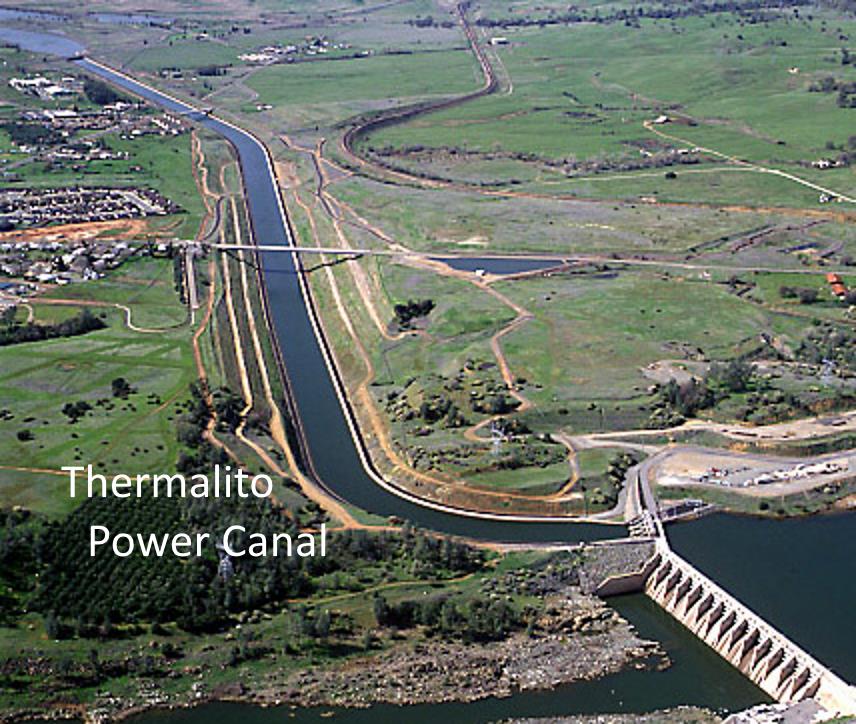
The Thermalito power canal is tiny by comparison with a small flow rate of only 430 m3/s.
(By comparison, the maximum flow rates we have seen thundering down the Oroville Dam Spillway in recent days of 100,000 cfs = 2830 m3/s, are only about 1/18th of the maximum flow through the mighty Strathdearn Power Canal)
The Strathdearn scheme could be powerful enough to serve all of Britain’s needs for energy storage and the needs of some of our European neighbours too.
The UK peak demand is about 55GW but the Strathdearn power capacity could be super-sized to supply up to 180GW – that’s plenty for future expansion needs too.
The Oroville-Thermalito complex supplies only about 1GW. That’s very little in comparison to what Strathdearn could supply.
So although the 2 dams – Oroville VS Strathdearn – are roughly the same size and the water impounded the same volume, the flows of water are very much more powerful in the Strathdearn scheme.
Although the Oroville Dam is the tallest dam in the US, the Oroville-Thermalito hydroelectric scheme is a modest scheme when considered next to the colossal scale of the Strathdearn Pumped-Storage Hydro Scheme.
LikeLike
Welcoming today’s post “How California’s electricity sector can go 100% renewable” on Energy Matters, I’m posting now here on my blog 2 concepts for California Energy Storage which I had developed and first published elsewhere in July 2017.
Lake Tahoe for energy storage https://scottishscientist.wordpress.com/folsom_tahoe/

Edmonston Pumped Storage Hydro Scheme https://scottishscientist.wordpress.com/edmonston/
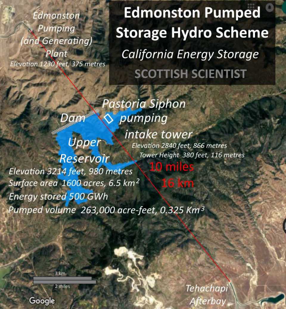
Whereas Energy Matters has today suggested serving California from the south from Mexico, it is also worth considering the option of serving California from the north from British Columbia in Canada, which has the ideal geography for pumped-storage hydroelectricity schemes, such as the adjacent freshwater Lakes Chilko and Tatlayoko; sites for sea-water schemes are plentiful in B.C. too.
BBC – “Sturgeon signs climate agreement with California”

I do hope that First Minister Nicola Sturgeon and Governor Jerry Brown and the people of Scotland and California are duly grateful and that they do appreciate these credible suggestions to use pumped-storage hydroelectricity schemes for the large scale of energy storage which is required for the transition to 100% renewable energy.
These serious and scientific energy storage proposals are modestly suggested in a manner that contrasts with the incredible hyperbole which accompanies the flogging by Tesla and others of inadequately small and far too expensive batteries as a “sticking plaster” “snake oil remedy” that cannot be fit for the purpose of achieving our ambitions to support low carbon energy to resist climate change.
Elon Musk – that don’t impress me much.
LikeLike
It is all about economics, it would likely be a lot cheaper to build an inter-connector to Norway and or Iceland and use a ‘cheaper’ hydro power scheme built where there are better mountains and shorter tunnels required for High Head schemes than Loch Strathdearn, (and believe it or not this is what is happening with National Grid investing in a non regulated businesses overseas in Norway).
I am all in favour of renewable electricity generating but I don’t wish to pay over the odds for my electricity. My business has to compete globally and having higher electricity costs and taxes CCL (Climate Change Levy) used to subsidise high cost re-newables make it more difficult. From a global perspective it would be better to invest in the Congo River Hydroelectric scheme 12 – 20 GW installed capacity which would run throughout the year and move the energy hungry businesses of Aluminium production there from all around the world and close it down fossil electricity production elsewhere used for Aluminium manufacture. Lets use a bit of Lateral thinking.
LikeLike
Plan for biggest-ever Australian pumped storage hydro scheme published. 😀
SNOWY 2.0 – 350 GWh / 2 GW (up to 8 GW) – http://www.snowyhydro.com.au/our-scheme/snowy20/
LikeLiked by 1 person
Austrian Utility Verbund to Expand Pumped-Storage Plant
LikeLike
In the course of my spirited defence of this proposal on Energy Matters last week, I made a few remarks about the alternative fresh-water variants of this scheme, although my final comments in our exchange haven’t as yet been approved by Euan for publication on his blog so I will quote here from my remarks there and reveal one of my two final comments.
“The location of the site for my Strathdearn Pumped-Storage Hydro-Scheme – particularly the upper reservoir, dam and power canal are located south of Inverness, rather than “south of Loch Ness”, in an area quite well-defined by the “Inverness South” ward of Highland Council.

The residents thereof would, I trust, be well-compensated for any compulsory land buy-outs, relocation costs or disruption caused by the re-engineering of the local environment.
The default version of the scheme proposes to use sea water. However, fresh water variants of the scheme are possible, using fresh water from Loch Ness and the River Ness.
The volume of Lake Oroville which is impounded by the Oroville Dam, which so spectacularly over-topped a couple of years ago, is about the same “giant” volume as the upper reservoir of the Strathdearn scheme at its grandest scale, as I commented upon at the time in my blog.
https://scottishscientist.wordpress.com/2015/04/15/worlds-biggest-ever-pumped-storage-hydro-scheme-for-scotland/comment-page-2/#comment-348
“The Oroville–Thermalito Complex is a group of reservoirs, structures, and facilities located in and around the city of Oroville in Butte County, California. The complex serves not only as a regional water conveyance and storage system, but is the headwaters for, and therefore perhaps is the most vital part of, the California Department of Water Resources’ State Water Project, the world’s largest publicly built and operated water and power development and conveyance system.”
So a scheme of that grand scale is demonstrably not “utterly bonkers environmental destruction on a grand scale” but is an entirely responsible re-engineering of the environment with irreplaceable benefits for the people, on a grand scale.
I propose that Strathdearn would be paid for by additional government borrowing, not by the tax-payer and not ever by diverting funds intended for “hip replacement operations and care for the elderly” or the like.”
“Assuming an active or live storage reservoir volume of 4.4 billion metres-cubed, then to fill or empty the upper reservoir from or to the lower reservoir in a day would require a flow rate of about 51,000 metres-cubed per second.
The discharge rate of the River Ness would not limit the operational flow rate between the upper and lower reservoirs of any of the fresh water variants of the scheme which I have in mind.
Whatever the flow rate of the River Ness is, it is not an issue and not a problem and I might suggest a bit of a red herring as far as the options for the Strathdearn scheme are (concerned).
There was no good reason me to consider the discharge flow rate of the River Ness in the first place and no good reason to remind you or anyone else of that either.
If you’d like to claim that the River Ness discharge rate could be a game-changer or particularly relevant for Strathdearn pumped storage hydro fresh-water variants then you’ve not explained why you think that?”
“Actually, Euan, I am very well aware of the issues at Coire Glas which empties into Loch Lochy, NOT into the sea.
Even the fresh-water variants of Strathdearn include a power canal etc. which BY-PASSES the River Ness, allowing for whatever controlled overflow into the sea is required.”
NOW REVEALED
Only with the fresh-water scheme variant which uses Loch Ness as the lower reservoir would the River Ness “dry run”, admittedly.
In which case, the Caledonian Canal could be extended for another 20+ miles along the length of Loch Ness to allow for continued navigation.
However, with the other fresh-water variant which uses an artificial fresh-water lagoon constructed in the Moray Firth, the levels in Loch Ness are UNCHANGED and the River Ness DOESN’T “run dry”.
In this case, the outflow from the River Ness would be diverted into the fresh-water lagoon.
The discharge flow rate from the River Ness would NOT limit the operational flow rate between the upper reservoir and the fresh-water lagoon but would only determine at commissioning how long (months) it takes to fill the fresh-water lagoon before the scheme can be operational at full energy storage capacity.
LikeLike
Rather than a canal, would it not be easier to construct a series of relatively small dams on the River Findhorn to create a chain of reservoirs? With the upstream end of each reservoir at the base of the next dam upstream, each (except the lowest) equipped with reversible pump turbines this would perform the function of the canal, but involve much less excavation and construction. You would probably still want to use tunnels to transport the water from the North Sea to a point north west of Moy to avoid disrupting the Findhorn valley downstream of here, with the lowest dam in the narrow part of the valley north east of Ruthven, roughly at 57.3764,-3.9560.
LikeLike
Welcome Ed.
Your suggestion seems to include building reservoirs to flood the populated A9 road and rail corridor where those transport links cross over the River Findhorn to avoid building a canal through there.
The A9 road and the railway viaduct bridges cross over the River Findhorn near Tomatin
The canal will be hard and expensive enough to win planning permission for, to buy the land for the canal and to compensate those people whose interests were damaged by the canal.
Higher compensation costs is why your reservoirs-instead-of-a-canal suggestion could be harder not “easier” and much more expensive than the canal, even if construction per se was easier and cheaper.
That’s why I propose a canal rather than reservoirs.
Your suggestion is worth evaluating at the design stage but it is simply one more of multiple variants of this scheme that really do need a government-funded feasibility study to determine which is the best, easiest, most cost-effective and which would win most support.
Further suggestions are welcome but for now may remain open, interesting questions but without definitive answers until the government takes an interest.
LikeLike
(1 terawatt-hour = 1000 gigawatt-hours)
You need 2 to 3 TeraWatt-Hours of pumped hydro?
STRATHDEARN PUMPED-STORAGE HYDRO SCHEME – Energy storage from 500 GWh (0.5 TWh) to 6,800 GWh (6.8 TWh)
LikeLike